சில நண்பர்களின் வேண்டுகோளுக்கிணங்க ஆட்டோடெஸ்க் ரேவிட் (Autodesk Revit In Tamil) தமிழில் கிடைக்கும் வகையில் தயார் செய்யப்பட்டுள்ளது. தேவைப்படும் நண்பர்கள் தொடர்புகொள்ளவும்.
Friday, October 3, 2014
Revit Training In Tamil - CD's Available
சில நண்பர்களின் வேண்டுகோளுக்கிணங்க ஆட்டோடெஸ்க் ரேவிட் (Autodesk Revit In Tamil) தமிழில் கிடைக்கும் வகையில் தயார் செய்யப்பட்டுள்ளது. தேவைப்படும் நண்பர்கள் தொடர்புகொள்ளவும்.
Creating simple parametric families in Revit
Creating simple parametric families in Revit
Today, I will be showing you how to create simple parametric families in Revit. This tutorial is for anyone learning Revit who hasn’t yet got into creating families. I will be continuing to post more family tutorials so keep checking back over the coming weeks for more. This tutorial will show you how to create a simple ‘cube family’ with a fixed elevation height with parametric width and height as well as material options.
The first thing you want to do, is to create a new generic family template. When deciding what template to use, you should take into consideration what kind of family you are creating. For example, if you are creating a light fixture, you would of course use the light fixture family template. Be sure to think about where the family will be hosted, if it will be hosted on the ceiling, make sure you also use a ceiling based family.

Once you have your generic family template loaded, you will want to tile the windows. (Be sure you have no other active projects open) The reason you want to do this is to give you a good overview of all relevant views when creating your family. Plan view, Elevation front, Elevation left (or right) and 3D view.

Now you should see 4 equally sized windows fitted to your screen. In case the view has been obscured, zoom to fit in each window (double click mouse wheel). Now the most important part about creating families is using reference planes. Reference planes are crucial when designing families, as these will act as your control dimensions / constraints. Create a square with 4 seperate reference planes as shown in the image below. Always remember to draw your reference planes clockwise, this will be important for future developments.

Now you have set constraints to the floor plan view of the project, it is now time to set some elevation height constraints. We do this with the use of dimensions (di), by adding a dimension line to our elevation view. If you have a certain height you want your cube to be, then measure it off here, otherwise, for now just follow the example shown in the images below.

Once we have set some dimensions on our reference planes, we want to give these dimensions a parameter. Parameters are used to give custom or fixed assets to our families. Now you want your elevation view, where you have just created a dimension to be active. Highlight your dimension and click on the dropdown menu next to label, as shown below. To start with, the only option you will see is ‘Add parameter…’
We are now going to add a parameter to this dimension line, constraining the elevation height of the cube. As shown in the image below, we will create a name for this dimension parameter ‘Height of cube’. Be sure the ‘Group parameter under’ option is set to ‘Dimensions’ In this case, we will keep it as a ‘Type’ parameter. This means that we can use this parameter to constrain the height of the family to the ‘Height of cube’ parameter, which you can see is ‘2214mm’.

Once you have created a parameter for your ‘Elevation left’ view, you will want to do the same thing for your dimension lines you created on the ‘Floor plan’ view. Click on the dimension defining the height and add a new parameter label. This time we will call the dimension ‘Height’ again checking it is set as a dimension. This time we will use an ‘Instance parameter’ so click the ‘Instance’ checkbox. Instance parameters will give the user of the family the option to define custom settings, in this case height for the cube. Follow the exact same steps mentioned above for your ‘Width’ dimension on the ‘Floor plan’ view. You will now have 3 dimension, with 3 new dimension labels.

Now, once our template is set up and constrained we are going to start creating some actual physical geometry. We do this of course with the Revit massing tools. As shown above, navigate to the ‘Design’ tab and click on ‘Solid Extrusion’. You now want to draw a box with the square line creation tool, covering the reference planes you have set, as shown in the image above. Before you finish your extrusion, you want to edit some of the extrusion properties.

We are now going to modify the ‘Extrusion End’ constraints, otherwise known as the elevation height, or extrusion height. Click on the small grey box at the end of the ‘Extrusion End’ bar. You will now see the ‘Associate Family Parameter’ dialogue appear. You will also see the 3 new paramaters you have just created. As we are now trying to define the extrusion height of the cube, we will select our ‘Height of cube’ parameter. Click OK. You will now see that the ‘Extrusion End’ bar is greyed out.

The final parameter we are going to add is to be for a material. The reason we do this, is so that the user of the family, in a project environment will be able to choose which material they want the family to be. For more detailed families it is possible to split the materials into different sections, but I will be discussing that in another post. For now, we want to add a parameter for the material. Simply click on the small box at the right side of the materials bar and click on ‘Add parameter…’ We will name this parameter ‘Cube Material’ and make sure it is set as a ‘Material and finishes’ parameter and set as an ‘Instance’.

You can now finish your extrusion by clicking on the green tick in the modify extrusion ribbon. You should now be seeing something similar to the image above. If not, make sure all of your views are active and zoomed to fit. You can now save this family. Revit > Save As > Family – I like to add all my custom families to a new folder I have created in the Autodesk library, that way they are all stored together, but you can choose to save it wherever suits you best.

Once you have saved your family, Use the Revit > Close button. You can now open up a new architectural project file template, or the project where you want to add your newly created family. You can now add your family the way you always would > Place component, locate your family and load it. You will now see your cube in a project view. Here you will be able to set some custom parameters, such as material, width and height. And that is it! Extremely simple, and good foundation knowledge for creating Revit families. I will be posting part 2 in my Revit familys series soon. Hope this has helped someone who is having trouble, or someone who is just starting to use Revit. Any problems or questions, just leave a comment!
Wednesday, September 3, 2014
Isolate Warnings - Apps For Revit 2015
Creates new 3D views to isolate and highlight the elements in the model that have warnings to assist in debugging the Autodesk® Revit® model.


https://apps.exchange.autodesk.com/RVT/en/Detail/Index?id=appstore.exchange.autodesk.com%3aisolatewarnings_windows32and64%3aen
https://apps.exchange.autodesk.com/RVT/en/Detail/Index?id=appstore.exchange.autodesk.com%3aisolatewarnings_windows32and64%3aen
Tuesday, February 4, 2014
Why can’t I select my curtain walls in Revit?
Why can’t I select my curtain walls in Revit?
Have you ever come across a situation where you can see the curtain wall elements in your Revit scene, but could not select them? To make this a little more confusing, you could select the components of the curtain wall, but not the wall itself? We have, especially when constructing the building envelope in files that were originally generated by someone else. Fortunately, this is an easy fix.
Let’s take a look at the situation.
Zooming into a curtainwall, you place your cursor near the perimeter and expect the curtain wall to highlight as it usually does.
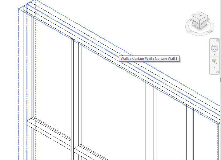
This time, the head mullion highlights, but not the overall curtain wall element. Pressing the Tab key cycles the selection through the nearby curtain wall components, but not the host object.

Trying to select the curtain wall with a selection window and filtering out everything except the wall itself seems like a solution but, as shown below, Walls are not shown as selected objects in the Filter dialog box along with the other objects.

What’s the problem? It’s not the wall itself, but the Discipline setting of the current view. With nothing selected, look at the Properties panel. In the Graphics area, if the Discipline value is set to Structural, the curtain walls cannot be selected. There are two solutions: The first, and preferable, is to change the Discipline parameter of the view to Architectural or any option other than Structural.

The second, and not recommended, option is to select the curtain wall then, in the Structural area of the Properties panel, check the Structural option. Curtain walls, by definition, are not load bearing and this solution may have ramifications regarding the structural design of the building.

We hope this information has been interesting and helpful. If you have any questions regarding BIM and curtain walls, don't hesitate to ask.
Adding Mullion Profile Parameters
Adding Mullion Profile Parameters
In the recent post "Custom Profiles" (http://curtainwallbim.blogspot.com/2013/02/custom-profiles.html), ghaeberle mentioned parametric curtainwall profiles and we'll take this opportunity to present the procedure for doing just that.
When creating the profiles for curtain wall mullions on a large project, you'll notice the number of mullions growing quickly. The captured mullion that you thought could be used in most places may need to be modified because of changes in the glass thickness, changes in the infill material (glass, terra cotta, aluminum composite panel (ACP), etc.), allowance for design features, or a change in the system, just to name a few. By adding parameters to the mullion profile family, changes can be made quickly and the new variation can be added to the project. Here's how:
1) Open a mullion profile family (.rfa). The one shown in the fig below is from the Custom Profiles tutorial on this site.

2) In the Properties panel of the Home tab, click the Family Types button.

3) This opens the Family Types dialog box. Each parameter must be named and then a dimension can be associated with each parameter. Click the Add button in the Parameters section of the Family Types dialog box.

4) In the Parameter Properties dialog box that opens, choose Type as the parameter type then enter a descriptive name in the Name field. Spaces are acceptable as parameter names, as are underscores and hyphens, but we don't recommend them. Underscores between words can offer a degree of visual continuity that a space doesn't and hyphens can be interpreted as minus (-) signs in some schedules. Make sure Length is selected as the Type of Parameter then click OK.

5) The parameter is added to the Dimensions category in the Family Types dialog box. Repeat step #4 until you've added all the parameters that you need. If you realize later that you missed one, you can repeat steps 2 - 4 to add it.

6) Add dimensions to your profile that correspond to the parameters you created. These are not visible in the project that the profile is loaded into, so you don't need to spend much time making them neat. You can also change the scale of the current view to reduce the size of the dimension.

7) Select a dimension then, from the Options bar, click the Label drop-down list and select the corresponding parameter.

8) The parameter name is added to the dimension name indicating that the dimension value is driven by the parameter value. Repeat step #7 to associate the remaining dimensions to the parameters. In the image below, you'll see that the overall system depth does not have an associated parameter. This value is driven by the sum of the System_Depth_FOG and Cap_Depth parameter values. This dimension cannot be locked as this would create a conflict should the other two dimensiond be modified.

9) In this example, the Mullion_Width and Cap_Width parameters should move the lines equally in opposite direction. To force this, add and place a multi-segment dimension from the left vertical mullion line to the reference line to the right vertical mullion line. Click the Toggle Dimension Equality icon (The EQ above the dimension). EQ replaces the actual dimension to indicate that the vertical mullion lines will remain equidistant from the reference line. Do this for the width of the cap as well.

10) Save the file then click the Family Types button to open the Family Types dialog box. The parameters are shown with their associated values. To modify a parameter, change the dimension in the Value column then click Apply to see the result in the view.

From here, you'll just need to save the file after the necessary parameter changes then load the family into the project. Remember, like any other family in Revit, it will overwrite all instances of the same name in the project. If this is to be an additional profile in the project, perform a Save As and give the profile a unique family name before loading it into the project. See the Custom Profiles post to see how to assign profiles to mullion types.
Saturday, February 1, 2014
Revit Parameters
I had a client email me about Parameters. They were having a tough time getting their head around the different types, so I thought I would make a quick post about it.
In Revit there are four kinds of Parameters:
System Parameters
Shared Parameters
Project Parameters
Family Parameters
Shared Parameters
Project Parameters
Family Parameters
System Parameters which include the two you highlighted are built-in to Revit and cannot be changed, but they are always available. This means they show in tags, schedules, projects, families, etc. Project Parameters are custom parameters you add to a project. When adding a project parameter, it is available to all objects of the specified category throughout the project and CAN appear in schedules but NOT tags. You create them with the command on the Manage tab of the ribbon. Family parameters are only available to the Family in which they are added. They do NOT show in tags or schedules nor to other Families of the same category. However, you can make a custom parameter (Project or Family) available to tags and schedules by making them a Shared Parameter. Shared Parameters are defined in an external text file (a Shared Parameter file) and you can access them also on the Manage tab. It is VERY important that you have a single shared parameter file for the entire firm to “share” thus the name. You do NOT want more than one Shared Parameter file. All this file is used for is to define the parameter. Once defined, it knows how to behave. So ALL shared parameters will be created from this single source file. The end users will not need to have access to, nor do they need to even know about the Shared Parameter file. Kind of like a recipe for your favorite cookies. You need the recipe to get the cookies right, but you don’t need the recipe to enjoy eating them.
If you think there is any chance that a custom parameter will want to be scheduled or tagged, you should make it a shared parameter. So on your titleblock, you need to make those custom parameters at LEAST a project parameter. This will tell Revit what to do with them. But consider making them Shared for additional flexibility down the road.
| Kind of Parameter | Who Creates it | Where does it live | Appear in Tags | Appear in Schedules | Description |
| System Parameters | Built in | Project and Family | Yes | Yes | Built-in to Revit, You cannot change it |
| Shared Parameters | User Defined | Project and Family | Yes | Yes | Custom Parameter created for the highest portability and flexibility |
| Project Parameters | User Defined | Project | No | Yes | Custom Parameter accessible to all objects in a Project |
| Family Parameters | User Defined | Family | No | No | Custom Parameter accessible only to the Family |
Hope that helps to clarify things a bit.
Thanks
paulaubin
Parameter in Revit
Parameter in Revit
Welcome to this revit.biz article on Parameters
Parameters are at the very heart of Revit. They are what make Revit so very powerful and flexible. Everywhere you look in Revit, you will see parameters at work…

Let’s take a section of wall. This wall is absolutely overflowing with parameters. If we look at it’s element properties, we can see…..

Each one of these settings is a parameter that we can change- either now or anytime in the future- and the effect on the wall will be made as soon as we confirm the change to the parameter. A very important thing to note is that parameters come in various “types”. An obvious type is length. For example, our wall has an Unconnected Height of 2000. The parameter “Unconnected Height” is a length parameter- if we were to enter the value “cherry pie” against Unconnected Height, Revit wouldn’t have a clue what we are trying to tell it- it is expecting a length here.
But if we look at “Room Bounding”…..

We either have a choice of ticked or unticked. This is still a parameter but it is of the type “Yes / No”, “0/1”, etc.
Likewise, if we look at the parameter “Top Constraint”…..

We can see that we have a choice from a pre-defined list.
Now the good news is that when you create your own custom components, you can create your own parameters- that you can name as you wish; and also specify what type you wish them to be.
So let’s go ahead and make a very simple component and then add a parameter that will allow us to modify the component within our project. For this exercise we are going to create a very simple 3D cube.
From a new Revit Project file, select File>New>Family..

From the File Explorer window, select “Generic Model”, and then “Open”….

This gives us a very basic template upon which to build our simple component.
Because we haven’t yet covered an explanation of the Family Editor (in which you are now in!) we will keep this example very simple- remember, all we are trying to demonstrate here is the use of your own parameters.
Go ahead and select “Solid Form > Solid Extrusion”…

…upon which Revit will enter Sketch Mode, allowing you to sketch the plan profile of you extrusion. Use the line tools to draw a square 1000 x 1000….

So that’s the shape for the base of our extrusion. Now we need to define the height- ie how far we wish it to be extruded. Click on “Extrusion Properties”…

And change Extrusion End from 250 to 500, like so….

Click OK, and then select Finish Sketch, to tell Revit to go ahead and form the Extrusion…

Revit has now created a box that is 1,000 x 1,000 in plan and 500 tall. Switch to View 1 (under 3D Views) and use the eye tool to spin the box around so that you can see it in 3D…

And there we have it! Our very first custom component. Let’s save it somewhere, so that we can use it again in the future. Select File > Save As. Choose where to save the component and give it a name. I’m going to save mine to the Desktop and call it “Small Table”….

And there it is. So let’s go ahead and put this component into a Project. Going back to Revit, select “Load into Projects”…

Upon selecting this command, you will be taken from the Family Editor back into the Revit Project File that you previously had open (before we started creating a new Family). To use our new component, just select “Component” from the “Basics” Design Bar….

You should immediately see our new component on the end of the cursor, ready to be placed! Go ahead and place 4 instances…..

Switch to the default 3D View to see our 4 tables in all their wonderful simplistic glory!

So there we have it. We’ve created a very simple component that can be used in any Revit Project. But this article was about Parameters! And we haven’t created any parameters? Adding parameters to our component would give us a great deal of flexibility, in terms of what we can do with it from within a Project.
As we know, our component has a base of 1,000 x 1,000 and a height of 500. But what if we wanted one of the instance to have a base of 200 x 750 and a height of 1,200? And another to have base of 100 x 2,000 and a height of 300? Well, we could create a new Family of each of the variations. But why would we want to do that when the underlying geometry of each variation is identical. Let’s just create some Parameters for the aspects that we wish to make flexible and then we can modify each instance to suit.
So far we have created a very simple custom component, which we then loaded into a Revit Project. Now we’re going to edit the Family that we previously created in order to add some Parameters to it
So first of all select one of the instances of our component….

and then select “Edit Family” from the Options Bar…..

Click OK to the prompt asking if you wish to “Open Small Table for Editing”. Revit now takes us back into the Family Editor where we can edit our custom component.
Switch back to a plan view of our component by double-clicking the “Ref. Level” view..
Before we go any further, let me explain what (exactly) we are going to do. We are going to add two parameters to our component. We are going to call the 2 parameters “Length” and “Width”. We are going to use these parameters to control the dimensions of our table, in plan.
In order to control our table size in plan, we need to be able to adjust the plan profile of the extrusion. So first of all we need to edit the extrusion we previously created. Select the geometry itself, ie click on our box- once selected, the box will highlight in red…

and then select “Edit” from the Options Bar….

This now takes us back into Sketch Mode, where we first sketched out the profile for our extrusion. In order to control the dimensions of this sketch we need to first add dimensions that we can then add our parameters to.
So go ahead and add two dimensions like so…

Now as they stand, these dimensions will have no effect on our component. They just confirm what we already know- that the profile for our extrusion is 1,000 x 1,000.
In order to “Control” these dimensions from within a Project, we need to add Parameters to each of the dimensions. Let’s do this now. Go ahead and select the bottom dimension. Make sure the dimension is selected- if it is, it will be highlighted in red….

Once selected, take a look at the Options Bar. You will notice a drop-down box called “Label”….

Click the black triangle to activate the drop-down menu. You will now see that you have the option to add a parameter to this dimension….

Go ahead and select “Add Parameter”. This will bring up the “Parameters Properties” control panel. You use this panel to tell Revit about the parameter you wish to define. Start off by naming the parameter- let’s call it “Length”….

While we have the Parameter Properties control panel open, let’s take a look around the rest of the options available to us. At the top of the panel is the option for this parameter to be either a Family Parameter or a Shared Parameter….

Family Parameters can only be accessed from within the Family in which they are created. Shared parameters are more powerful and allow us to share their data between families and also have it automatically populate schedules and tags. For our example, leave the Parameter Type set as “Family Parameter”
Moving back down to the bottom of the panel again, we see the following…

We already know about “Name”- this is what we want to call our Parameter.
“Group Parameter under” allows us to select where our parameter will appear, when we access it via the Element Properties box- go ahead and change this to “Dimensions”.
The Instance and Type radio buttons allow us to specify whether this parameter is an Instance Parameter or Type Parameter. Let’s change it to an Instance Parameter- this will let us have a unique value for this parameter, for each instance of the component in the model.
“Type of Parameter” allows us to choose what type of parameter we want it to be. You will recall from part A of this article that there are many types of parameter- ie “Yes / No”, etc. In our example, “Type of Parameter” is already set to Length and is greyed out. This is because we are adding a parameter to a dimension- and dimensions can only accept parameters of the type “Length”. It wouldn’t make sense to add a “Yes / No” parameter to a dimension, would it?
Once you have made the changes listed above, go ahead and click OK. You will notice that Revit has added the name of the parameter to the dimension. It also displays the current value of the parameter- in this case 1000.

Now you need to go through the above process again for the other dimension. This time name the dimension “Width”. Make sure you make all the other changes as before- ie select “Instance” as the parameter Type, etc.

So there we have it. The profile that defines the plan of our extrusion is now controlled by two parameters that we have created. Go ahead and select Finish Sketch to create the extrusion. And what do you know? Our component does not look any different than it did before! Don’t worry- the difference will become evident when we work with our component from within a project. So let’s do that now.
Because we have modified our component in the Family Editor, we need to load the current (new) version into a project- this will automatically update all old versions of the component already in the project. So go ahead and select “Load into Projects”. Upon doing so, you will receive the following warning….

This is just warning us that a version of this component is already in use in our project. Click OK to overwrite the old version.
Again, no visible difference to our components! Go ahead and select one of the components- and then select the Element Properties…..

If you look at the Element Properties panel, you will see our two new parameters listed under “Dimensions” (because we chose to “Group under Dimensions”). Because we made them Instance Parameters, we can now change their values for each instance of the component within the model. So go ahead and test it out- change the values of our parameters for each of the 4 instances of the component…..

So there we have it- our first custom parametric component! Very simple, I know- but we’ve covered some very important, fundamental concepts. The ability to create dynamic geometry than can be easily modified and reused is a very powerful aspect of Revit.
Subscribe to:
Comments (Atom)